Stock Spring Tolerances and Engineering Notes
Imperial/Metric Conversions
Spring rate: ± 10% ; Solid Height Tolerance: +5%, no lower limit
*Except where noted to meet DIN 2098
This O.D. table not applied to Lite Pressure, HEFTY Die, REDUX, or MIL-SPEC
Stock Lite Pressure (LP Series) Outside Diameter (OD) Tolerances
Imperial/Inch
|
| .201" |
to |
.300" |
± |
.008" |
| .301" |
to |
.500" |
± |
.010" |
| .501" |
to |
.850" |
± |
.020" |
| .851" |
to |
1.125" |
± |
.025" |
| 1.126" |
to |
1.460" |
± |
.030" |
| 1.461" |
to |
1.687" |
± |
.040" |
| 1.688" |
to |
1.937" |
± |
.055" |
| 1.938" |
to |
2.375" |
± |
.070" |
| 2.376" |
to |
2.875" |
± |
.090" |
Metric
|
| 5.11mm |
to |
7.62mm |
± |
.20mm |
| 7.65mm |
to |
12.70mm |
± |
.25mm |
| 12.73mm |
to |
21.59mm |
± |
.51mm |
| 21.62mm |
to |
28.58mm |
± |
.64mm |
| 28.60mm |
to |
37.08mm |
± |
.76mm |
| 37.11mm |
to |
42.85mm |
± |
1.02mm |
| 42.88mm |
to |
49.20mm |
± |
1.40mm |
| 49.23mm |
to |
60.33mm |
± |
1.78mm |
| 60.35mm |
to |
73.03mm |
± |
2.29mm |
Stock MS24585 Compression Outside Diameter (OD) Tolerances
Imperial/Inch
|
| .120" |
to |
.240" |
± |
.005" |
| .300" |
to |
.500" |
± |
.008" |
| .550" |
to |
.850" |
± |
.015" |
Metric
|
| 3.05mm |
to |
6.10mm |
± |
.13mm |
| 7.62mm |
to |
12.70mm |
± |
.20mm |
| 13.97mm |
to |
21.59mm |
± |
.38mm |
Stock Extension Outside Diameter (OD) Tolerances*
Imperial/Inch
|
| .063" |
to |
.098" |
± |
.004" |
| .109" |
to |
.299" |
± |
.005" |
| .300" |
to |
.500" |
± |
.010" |
| .501" |
to |
.850" |
± |
.015" |
| .851" |
to |
1.125" |
± |
.020" |
| 1.126" |
to |
1.250" |
± |
.030" |
| 1.251" |
to |
1.500" |
± |
.040" |
| 1.501" |
to |
1.750" |
± |
.050" |
| 1.751" |
to |
2.000" |
± |
.055" |
Metric
|
| 1.60mm |
to |
2.50mm |
± |
.10mm |
| 2.77mm |
to |
7.59mm |
± |
.13mm |
| 7.62mm |
to |
12.70mm |
± |
.25mm |
| 12.73mm |
to |
21.59mm |
± |
.38mm |
| 21.62mm |
to |
28.58mm |
± |
.51mm |
| 28.60mm |
to |
31.75mm |
± |
.76mm |
| 31.78mm |
to |
38.10mm |
± |
1.02mm |
| 38.13mm |
to |
44.45mm |
± |
1.27mm |
| 44.48mm |
to |
50.80mm |
± |
1.40mm |
Stock MS24586 Extension Outside Diameter (OD) Tolerances
Imperial/Inch
|
| .120" |
to |
.240" |
± |
.005" |
| .300" |
to |
.500" |
± |
.008" |
| .650" |
to |
1.000" |
± |
.015" |
Metric
|
| 3.05mm |
to |
6.10mm |
± |
.13mm |
| 7.62mm |
to |
12.70mm |
± |
.20mm |
| 16.51mm |
to |
25.40mm |
± |
.38mm |
Stock Torsion Engineering Notes and Tolerances
General Notes
-
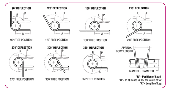
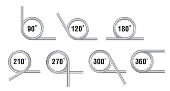
Lengths of legs are shown as "A" in sketches below.
-
Please note: "R" (radius in inches) where force is applied is always 1/2 of "A" (Length of Leg). Dotted lines of legs show loaded position where values of "T" (Torque) will be achieved at "R" (Radius).
-
To translate torque values to direct load: Use Formula - P = T/R P = Load applied at Radius (R) T = Torque Example: Part LTL 012A 01, what is the load where R = .187? Using P = T/R = .050/.187 = .267lbs.
-
To calculate torque values other than those listed (Position of Ends), a direct proportion may be used. Example: Part LTL 012 A 01. Torque shown in catalogue listing is .050 in-lbs. for 90° deflection; therefore, torque for 45° would be .025 in-lbs.
-
Inspection of Load - Loads should always be checked at the Radius ("R" value)

-
Mandrel Size: Generally, torsion springs are used over a mandrel (shaft or arbor). The column "Suggested Mandrel Size, Inches", allows approximately a 10% clearance for the various deflections shown in examples below. If you require greater deflections, we suggest a suitable reduction in the mandrel size.
-
Direction of Wind: Good design dictates that torsion springs should be used in the direction that winds the coil. When ordering be sure to choose either LTL (Left Hand Wound) or LTR (Right Hand Wound) for required application.

Stock Torsion Outside Diameter (OD) Tolerances
Stock REDUX Wave Spring Engineering Notes and Tolerances
Stock REDUX Wave Spring Engineering Notes and Tolerances
General Notes
-
Stock REDUX Wave Springs are made of material 17-7PH Stainless Steel
-
Maximum operating temperature is 650 degrees F
-
Nominal Load is the approximate force at the Working Height. Be advised springs may take a set if compressed below the Working Height.
-
The Number of Turns comprises a continuous coil; there is no welding or adhesive between waves.
-
Ends turns are regular & wavy. Flat & shim ends can be offered in a special order.
Stock REDUX Wave Spring Tolerances
Rate: ± 25%
The Outside Diameter and Inside Diameter are reference only. REDUX Wave Springs are manufactured to operate with the specified mating Hole Diameter and Rod Diameter.


 Sign Up/Log In


